3D Printing

3D Thursday: Printing Our Own Designs

3D Thursdays are an on-going set of blog posts that dig into the world of 3D printing as we develop our knowledge and skills of the process and then present them to you to further both your understanding and ours.

An example of CAM software in ReplicatorG (image from MakerBot)

An example of CAM software in ReplicatorG (image from MakerBot)

Since we began this 3D Thursday series, we’ve explained the basics of how it works, how to print pre-made objects and what exactly slicing means in regards to the design process.  While the previous post outlined specific slicing settings, the following post will give a better overview starting with theory and ending with physical objects.

Now that we’ve covered those aspects, it’s time to expand our 3D printing knowledge. Rather than printing something via Thingiverse that someone else made, we began to design our own 3D objects in Google Sketchup. Sketchup is a similar design program to AutoCAD, except it’s significantly cheaper and much more user friendly for those who didn’t attend architecture or engineering school.

You can give the software a try with a free trial run, but if you plan on creating your own prints regularly, you’re going to need a program like this for 3D modeling. AutoCAD is generally thought of as software for creating blueprints, but also has the ability to do 3D design like Sketchup. While AutoCAD may appear cheaper looking at their respective sites, keep in mind purchasing Sketchup is a straight license, whereas AutoCAD is a subscription service that requires payment at a monthly, quarterly or yearly rate.

Once you have a design made and ready to be converted into a 3D file, it’s time to use a computer-aided manufacturing (CAM) program that converts the file types into .STL and GCode format that the 3D printer can read. There is a variety of programs that can do this, with many of them being free open-source software that anyone can download and use. These programs are mentioned in the previous slicing post, which you can view here.

We’ve mentioned Slic3r as one of these programs and we have also used ReplicatorG. We have found it very intuitive and self-explanatory. While there is a learning curve for these programs, a trial-by-error approach is best anyways since every 3D printer seems to have its own temperament and small quirks that need to be adjusted on the fly.

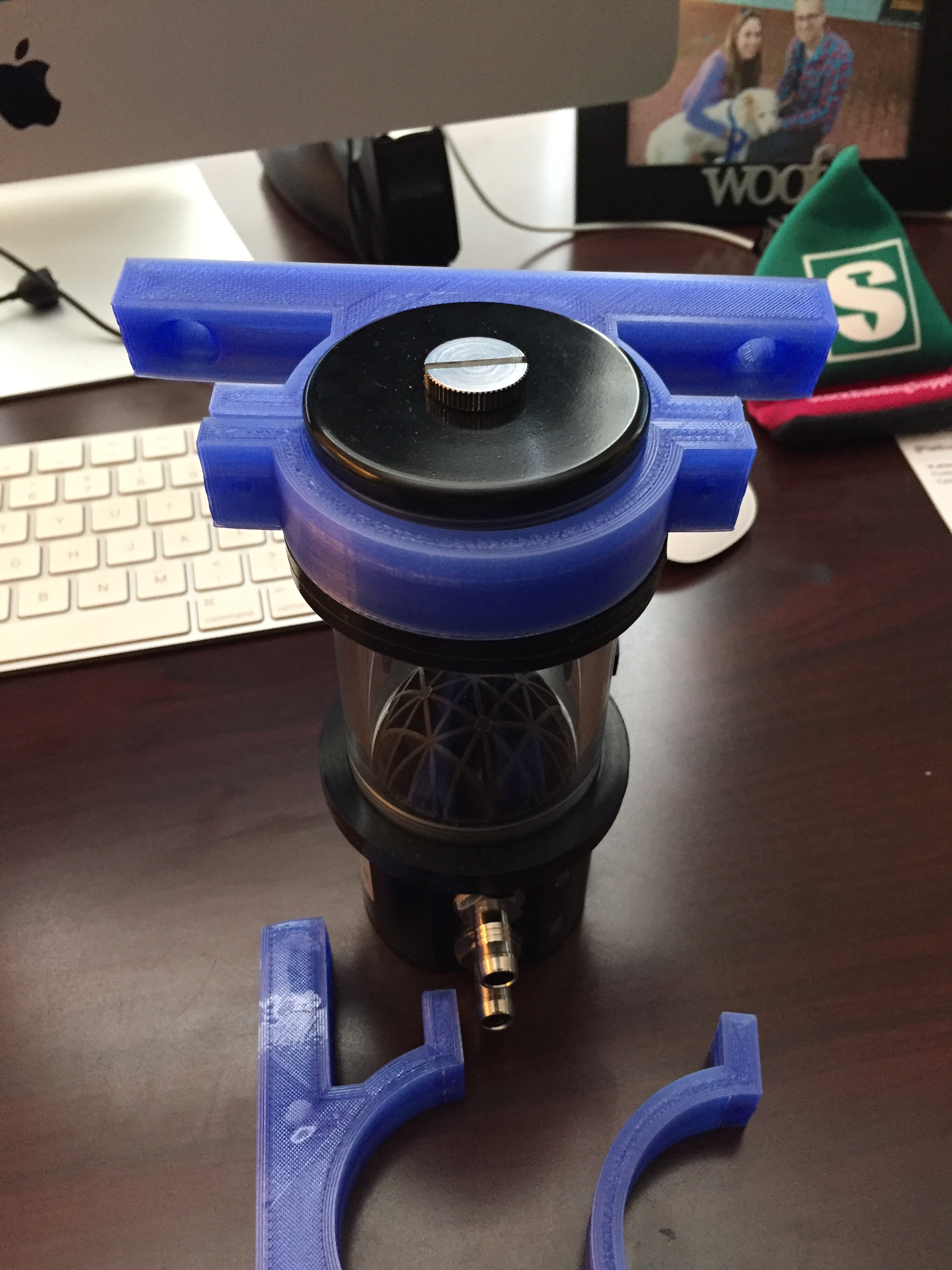
Now that we’re out of the explanatory portion, let’s show you some items that we designed from scratch. The first is a bracket of sorts that mounts a water pump onto our CNC machine so we can use a water-cooled spindle with our machine. The pump needed to be close to the spindle, so we made a 3D object that would allow the pump to move with the spindle, whether it was side-to-side or up and down.

The design process was fairly simple and required a few measurements of the water pump itself. We needed both the outer diameter dimensions of the pump as well as its depth to ensure the mount stuck out far enough to avoid entanglement with the Z-axis.

We also had to ensure the proper size holes were in position for the attachment to the axis and the secondary piece to connect to the main piece. Luckily the filament can be shaved down quite easily without ruining the object, so threading a screw through that is slightly too large isn’t a huge problem. The first print through proved to be slightly too small on the inside of the curve, so with some tweaking to the arc, the second print was spot-on.

The other pieces we made for our CNC machine were bracket mounts for an external cooling fan. These pieces were much easier to design and print, since they were essential just ‘L’ shaped pieces with the necessary depth for holding the fan and holes for attaching the fans existing holes to the brackets. Once again, our first print didn’t quite lineup, but a slight revision was just enough to make it work.

Lastly, we also designed a case for a piece of electronics called Raspberry Pi that we needed to install inside an old PC. The case required several specific openings to allow for cable connections of the Pi device as well as four exact holes that lined up with the PC’s motherboard to screw it in place without hurting the existing electronics. This design was one of those trial-by-error pieces that started extremely frustrating.

While we were able to get exact measurements for the Raspberry Pi itself, the more difficult measuring came to the attachment inside the computer. The screw holes took at least four prints, which we were able to stop early into the process when we noticed it wasn’t lining up. Eventually the device was both able to slip into the case as well as lineup with the screw holes, which is obviously the intended goal and end result we wanted was the computer booting up properly and all electronics starting up. Once it was all fitted in place, we were finally able to breathe a sigh of relief for completing this phase of learning 3D printing.

Our above-mentioned designs can be found on my Thingiverse account here. Feel free to download any of our personal creations or our remixed ones. If you make any of them, leave a comment or suggestions for improvement if you have any. 

3D Thursday: Slicing settings for first time designers

3D Thursdays are an on-going set of blog posts that dig into the world of 3D printing as we develop our knowledge and skills of the process and then present them to you to further both your understanding and ours.

Once we mastered the very basics of the 3D printing process, it was time to take these steps and extrapolate them into designing and printing our own pieces. Printing pre-made items is a much simpler task when all you are doing is downloading a file and importing into your 3D slicer program, all with previously defined settings.

FIGURE #1 SCREENSHOT OF SLIC3R PROGRAM'S PRINT SETTINGS

FIGURE #1 SCREENSHOT OF SLIC3R PROGRAM'S PRINT SETTINGS

This post will focus on what exactly slicing means when it comes to 3D printing and how the changes apply when you start going off on your own.

Slicing is a term mentioned before with very little explanation. Slicing programs like Slic3r are the go-betweens to take 3D files we built in Google Sketchup and AutoCAD and turn them into .x3g files that the printer can read.

Slicing imports your design and then gives you hundreds of options as to how you want your item to print. The first steps are setting up your ideal settings with varying results exclusive to each piece printed. [SEE FIGURE 1 & 2]

FIGURE #2 OF SLIC3R PROGRAM'S PRINT SETTINGS

FIGURE #2 OF SLIC3R PROGRAM'S PRINT SETTINGS

Some of the variables include ‘rafts’ which are the first things printed that literally create a plastic raft between the heated bottom plate and the beginning of the object printed. Think of it like a wood pallet used in warehouses—it elevates it off the ground just enough that the real product doesn’t get ruined. [WE ALMOST ALWAYS USE RAFTS WITH 4 LAYERS.]

In conjunction with the rafts is indicating both the ‘first layer height’ and the overall ‘layer height.’ The first layer height is typically a bit thicker than the rest of the layers and prevents any heat warping that may occur at the beginning of the print. This is commonly seen when you have sharp edges that get so much heat that the corners contort and curl upwards. When this happens, it might be prudent to stop the print and reevaluate the thickness of your rafts and first layer height before further mistakes are made. [OUR FIRST LAYER HEIGHT IS ALWAYS 0.35mm ALL REMAINING LAYERS ARE 0.2mm.]

Another factor is ‘supports,’ which is literally what it sounds. Extra little pieces are printed that fill the gaps of parts that have little structural support while still in the printing process; they are just big enough to provide stability, but small enough that you can break them off after the process is complete. [WE ALWAYS USE SUPPORTS UNLESS THE OBJECT IS COMPLETELY SOLID AND HAS NO AREAS WHERE DROOPING MAY OCCUR.]

Next comes ‘perimeters.’ This is another term simply named, but can have a multitude of factors dependent upon what you are trying to print. Perimeters are the outer-most layers of the print and typically the thickest parts of the item. It’s at this point where you will quickly see whether or not the printing is going to resemble what you want it to be.

The perimeters create the structure necessary for the next step of determining the printing ‘infill,’ which will be explained next. Before infill begins, the ‘solid layers’ setting also has to be defined, which is just like perimeters but refers to the top and bottom of the print, basically sealing it all up on every side. [WE USE A MINIMUM OF 4 PERIMETERS AND 3 TOP AND 3 BOTTOM SOLID LAYERS, BUT OFTEN UP THAT NUMBER IF WE NEED TO BE STURDIER IF REGULAR FORCE WILL BE APPLIED TO THE OBJECT.]

The aforementioned ‘infill’ majority of the printing process and refers to all of the printing substance within all of the perimeters, both horizontally and vertically. Infill has several settings, the first being the ‘fill density,’ which is the percentage of space you want filled. 100% infill would literally be every single layer is one complete slab on top of each other and would just be a back and forth filling each layer.     [ SEE FIGURE 3 BELOW]

Whenever you use an infill of anything less than 100%, you also have to choose a ‘fill pattern’ and the ‘top/bottom fill pattern.’ These patterns vary and include: line, Hilbert curve, honeycomb, 3D honeycomb, rectilinear, Octagram Spiral and Archimedean Chords. These all may seem like complicated math terms, but in reality are just various non-solid methods of giving the printed item inner strength. Without explaining every version of pattern, honeycomb is pretty self-explanatory, as is line, but check out [FIGURE 4 BELOW] to see a visual understanding. [WE TYPICALLY USE A FILL DENSITY OF 40%, FILL PATTERN OF HILBERT CURVE AND A TOP/BOTTOM FILL PATTERN OF CONCENTRIC.]

[FIGURE #3] IMAGE FROM DEVIANTART.COM

[FIGURE #3] IMAGE FROM DEVIANTART.COM

[FIGURE #4]      IMAGE FROM THINGIVERSE.COM

[FIGURE #4]      IMAGE FROM THINGIVERSE.COM

 There are also some standard infill settings that we rarely change within the Slic3r program such as: ‘Combine infill every: 1 layer,’ ‘Solid infill every: 0 layers,’ ‘Fill angle: 45 degrees’ and ‘Only retract when crossing perimeters.’

There are dozens of other general settings that can be tweaked depending on what you preferences are and are typically changed with some trial and error printing. We rarely mess with the rest since we are still fairly new to the process, but the last settings we make sure to change are the ‘filament settings’ [ENTIRELY BASED ON WHAT FILAMENT YOU PERSONALLY BUY AND USE; OURS IS 1.75mm.] and ‘extruder and bed temperature’ [WE’VE LEARNED TO INCREASE THE TEMPS. SLIGHTLY FROM STANDARD TO ENCOURAGE THE FIRST FEW LAYERS TO PRINT FLAT: EXTRUDER TEMPS @ 240 DEGREES CELSIUS AND BED TEMPS. @ 115 DEGREES CELSIUS.]

This may seem like a lot—that’s because it is to start. It took us probably 50 prints before we started getting exactly what we wanted and we still struggle when it comes to printing new pieces. Next post we’ll dig more into our own creations now that we have a decent understanding of how to properly prepare the 3D printing files.

3D Thursday: An Introduction to 3D Printing

At this point in the technology world, almost everyone is aware of 3D printing. While most may think it’s just a high-tech hobby, the future of 3D printing has already surpassed initial speculation. It’s now possible to use 3D printing technology in other mediums aside from plastic and on a much larger scale if desired. The most popular method of 3D printing is called ‘extrusion,’ which essentially means that constantly heated nozzles warm to a temperature where it liquefies the material to produce a gooey substance that is able to conform to the design you’ve created.

THE FLASHFORGE CREATOR PRO

THE FLASHFORGE CREATOR PRO

AN EXAMPLE OF A 3D PRINTED PROSTHETIC LIMB

AN EXAMPLE OF A 3D PRINTED PROSTHETIC LIMB

 A CLOSE-UP LOOK AT EXTRUDING 

 A CLOSE-UP LOOK AT EXTRUDING 

Without going into the entire backstory of 3D printing, the Wikipedia page gives a lengthy history of the conception of 3D printing dating back to the 19th century.  Today, 3D printing can be used with polymer plastics, rubber, concrete, modeling clay and metal alloys.  Check out this awesome video here of a concrete 3D printed house.

One of the most popular industries using this technology is the creation of intricate arms and legs in the prosthetic field. The advantage to this method of prosthetic is that they actually resemble the limb, rather than just a piece of metal with a hook as a hand or a wooden block as a foot. 3D prosthetics extend beyond the basics, including functioning fingers, wrists and ankles, all with a customized design that actually looks cool too. 

While we at Black Rock Holdings aren’t creating prosthetics, we have begun experimenting with a FlashForge Creator Pro 3D printer we got for around $1,200. This style of printer has dual extrusion nozzles with a heated plating bed and an X, Y and Z-axis referred to as a “Cartesian Printer.”

Our early prints were a bit advantageous, attempting to print a homemade CNC Machine we found on Thingiverse, an online community with open-source designs others can replicate using their printer.

This CNC machine was just too complicated for our first real build. While it visually represented what it should look like, our skills in using the 3D printing design software Slic3r were still minimal and our pieces just didn’t seem to measure out properly.

As we experiment with the 3D printer, we’ll keep you updated as we learn more so we can relay our familiarities. The idea of a world where everyone has a 3D printer is inevitable, as more and more concepts are created. Even now, scientists and designers are working on creating 3D printers that are able to create edible material as well as print your own clothing from home.  The future of 3D printing is nigh and you’ll want to get onboard sooner than later.